CircuiTikZ
Preamble
\usepackage[european,straightvoltages]{circuitikz}
\usetikzlibrary{math} \usepackage[european,straightvoltages]{circuitikz}
\usetikzlibrary{math} Use _^<> to change direction and position of labels
\draw
 (0,0) to[sV, v=$v$] ++(0,3)
to[Do, l=$D$, i=$i_d$] ++(5,0)
to[R, l_=$R$, v^>=$e_d$] ++(0,-3)
-- (0,0);
\draw
 (0,0) to[sV, v=$v$] ++(0,3)
to[Do, l=$D$, i=$i_d$] ++(5,0)
to[R, l_=$R$, v^>=$e_d$] ++(0,-3)
-- (0,0);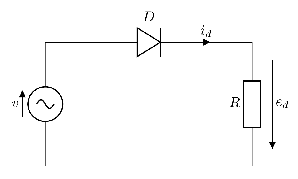
Jumping crossing, Add text
\tikzmath{\w1 = 6; \h1 =2; \w2=2.5; \h2=2;
    \h3=0.5; \h4=1; }

\draw
(0,0) to[sV, v=$\dot{E_a}$] ++(0,\h1)
to[short, i=$\dot{I_a}$] ++(\w1,0)
to[R=$Z_a$, -*] ++(0,-\h1) %Add a node
to[R=$Z_n$, -*, i_=$\dot{I_n}$] (0,0);
\draw
(0,0) to[sV, v=$\dot{E_c}$] ++(-\w2,-\h2)
-- ++(0,-\h4)
to[short, i=$\dot{I_c}$] ++(\w1,0)
-- ++(0,\h4)
to[R, l_=$Z_c$] ++(\w2,\h2);

\node at (\w1-\w2,-\h2-\h3)[jump crossing](X){}; %Jump crossing
\draw (X.east) to[short, i=$\dot{I_b}$] ++(2*\w2,0) %Start from the crossing
-- ++(0,\h3)
to[R=$Z_b$] (\w1,0);
\draw (0,0) to[sV, v_=$\dot{E_b}$] ++(\w2,-\h2)
-- ++(0,-\h3)
-- (X.west);

\node at (0,0)[above=1mm, left=1mm] {N};
\node at (\w1,0)[above=1mm, right=1mm] {N'};\tikzmath{\w1 = 6; \h1 =2; \w2=2.5; \h2=2;
\h3=0.5; \h4=1; }
\draw
(0,0) to[sV, v=$\dot{E_a}$] ++(0,\h1)
to[short, i=$\dot{I_a}$] ++(\w1,0)
to[R=$Z_a$, -*] ++(0,-\h1) %Add a node
to[R=$Z_n$, -*, i_=$\dot{I_n}$] (0,0);
\draw
(0,0) to[sV, v=$\dot{E_c}$] ++(-\w2,-\h2)
-- ++(0,-\h4)
to[short, i=$\dot{I_c}$] ++(\w1,0)
-- ++(0,\h4)
to[R, l_=$Z_c$] ++(\w2,\h2);
\node at (\w1-\w2,-\h2-\h3)[jump crossing](X){}; %Jump crossing
\draw (X.east) to[short, i=$\dot{I_b}$] ++(2*\w2,0) %Start from the crossing
-- ++(0,\h3)
to[R=$Z_b$] (\w1,0);
\draw (0,0) to[sV, v_=$\dot{E_b}$] ++(\w2,-\h2)
-- ++(0,-\h3)
-- (X.west);
\node at (0,0)[above=1mm, left=1mm] {N};
\node at (\w1,0)[above=1mm, right=1mm] {N'};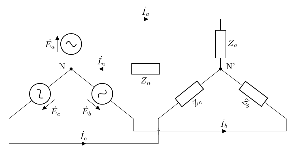
A smaller resistor
\tikzmath{\w1 = 5; \h1 =2; \w2=2; \h2=1.2;
    \h3=1.3; }

\draw
(-\w1,\h1) to[short, i=$\dot{I_a}$] ++(\w1-\w2,0)
-- ++(\w2,0) %To align Ia with Ic
to[R=$Z_a$, -*] ++(0,-\h1);
\draw
(0,0) to[R=$Z_b$] ++(\w2,-\h2)
-- ++(0,-\h3)
-- ++(-2*\w2,0)
to[short, i<=$\dot{I_b}$] +(-\w1+\w2,0);
\draw
(0,0) to[R, l_=$Z_c$] ++(-\w2,-\h2)
to[short, i<=$\dot{I_c}$] +(-\w1+\w2,0);
\draw %A smaller resistor
(0,0) to[R, resistors/scale=0.6, i=$\dot{I_n}$] +(0,-1.5) node[ground]{};\tikzmath{\w1 = 5; \h1 =2; \w2=2; \h2=1.2;
\h3=1.3; }
\draw
(-\w1,\h1) to[short, i=$\dot{I_a}$] ++(\w1-\w2,0)
-- ++(\w2,0) %To align Ia with Ic
to[R=$Z_a$, -*] ++(0,-\h1);
\draw
(0,0) to[R=$Z_b$] ++(\w2,-\h2)
-- ++(0,-\h3)
-- ++(-2*\w2,0)
to[short, i<=$\dot{I_b}$] +(-\w1+\w2,0);
\draw
(0,0) to[R, l_=$Z_c$] ++(-\w2,-\h2)
to[short, i<=$\dot{I_c}$] +(-\w1+\w2,0);
\draw %A smaller resistor
(0,0) to[R, resistors/scale=0.6, i=$\dot{I_n}$] +(0,-1.5) node[ground]{};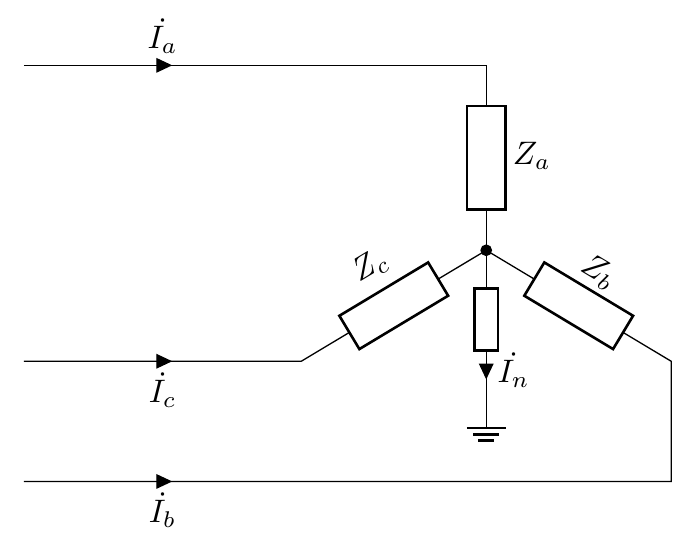
Switch
\tikzmath{\w1=3.5; \w2=1.4; \h=2.5;}

\draw
(0,0) to[battery2, invert, l=$E$] ++(0,\h) %Use invert to change direction
to[cute opening switch] ++(0.5*\w1,0)
to[R, l=$R_1$] ++(0.5*\w1,0)
to[capacitor, l_=$C$] ++(0,-\h)
-- +(-\w1,0);
\draw
(\w1,\h) -- ++(\w2,0)
to[R, l_=$R_2$, v^>=$i$] ++(0,-\h) %Floating current label
-- +(-\w2,0);

\node at (0.25*\w1,\h)[above=4mm, left=1mm] {S};
\node at (0.25*\w1,\h)[above=4mm, right=2mm] {$t$=0};\tikzmath{\w1=3.5; \w2=1.4; \h=2.5;}
\draw
(0,0) to[battery2, invert, l=$E$] ++(0,\h) %Use invert to change direction
to[cute opening switch] ++(0.5*\w1,0)
to[R, l=$R_1$] ++(0.5*\w1,0)
to[capacitor, l_=$C$] ++(0,-\h)
-- +(-\w1,0);
\draw
(\w1,\h) -- ++(\w2,0)
to[R, l_=$R_2$, v^>=$i$] ++(0,-\h) %Floating current label
-- +(-\w2,0);
\node at (0.25*\w1,\h)[above=4mm, left=1mm] {S};
\node at (0.25*\w1,\h)[above=4mm, right=2mm] {$t$=0};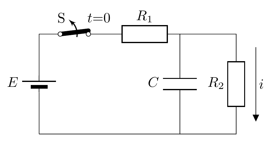
Two-terminal switch, Positioning
\tikzmath{\w1=3.5; \w2=1.4; \h=2.5;}

\draw
(0,0) to[battery2, invert, l=$E$] ++(0,\h)
to[cute inductor, l=$L$] ++(\w1,0) node[cute spdt down arrow, anchor=in](S){};
\draw (S.out 1) -- ++(\w2,0) coordinate (P1);%Store the current coordinate to P1
%Find the intersection between a vertical line through P1
%and a horizontal line through (0,0)
\draw (P1) to[R, l=$2R$] (P1 |- {(0,0)})
-- (0,0);
\draw (S.out 2) -- ++(0.2*\w2,0) coordinate (P2);
\draw (P2) to[R, l=$R$] (P2 |- {(0,0)});

\node at (\w1,\h)[below=4mm, left=-2mm] {S};
\node at (\w1,\h)[above=3mm, left=-2mm] {$t$=0};\tikzmath{\w1=3.5; \w2=1.4; \h=2.5;}
\draw
(0,0) to[battery2, invert, l=$E$] ++(0,\h)
to[cute inductor, l=$L$] ++(\w1,0) node[cute spdt down arrow, anchor=in](S){};
\draw (S.out 1) -- ++(\w2,0) coordinate (P1);%Store the current coordinate to P1
%Find the intersection between a vertical line through P1
%and a horizontal line through (0,0)
\draw (P1) to[R, l=$2R$] (P1 |- {(0,0)})
-- (0,0);
\draw (S.out 2) -- ++(0.2*\w2,0) coordinate (P2);
\draw (P2) to[R, l=$R$] (P2 |- {(0,0)});
\node at (\w1,\h)[below=4mm, left=-2mm] {S};
\node at (\w1,\h)[above=3mm, left=-2mm] {$t$=0};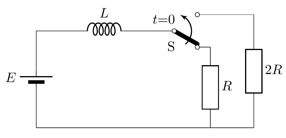
Current source
%Preamble: \usepackage[european,americancurrents]{circuitikz}
\tikzmath{\w1=2.3; \w2=1.7; \h=2.5;}

\draw
(0,0) to[I, l=$J$] ++(0,\h)
to[cute opening switch] ++(\w1,0)
to[capacitor, l_=$C$] ++(0,-\h)
-- +(-\w1,0);
\draw
(\w1,\h) -- ++(\w2,0)
to[R, l_=$R$] ++(0,-\h)
-- +(-\w2,0);

\node at (0.5*\w1,\h)[above=4mm, left=1mm] {S};
\node at (0.5*\w1,\h)[above=4mm, right=2mm] {$t$=0};
%Preamble: \usepackage[european,americancurrents]{circuitikz}
\tikzmath{\w1=2.3; \w2=1.7; \h=2.5;}
\draw
(0,0) to[I, l=$J$] ++(0,\h)
to[cute opening switch] ++(\w1,0)
to[capacitor, l_=$C$] ++(0,-\h)
-- +(-\w1,0);
\draw
(\w1,\h) -- ++(\w2,0)
to[R, l_=$R$] ++(0,-\h)
-- +(-\w2,0);
\node at (0.5*\w1,\h)[above=4mm, left=1mm] {S};
\node at (0.5*\w1,\h)[above=4mm, right=2mm] {$t$=0};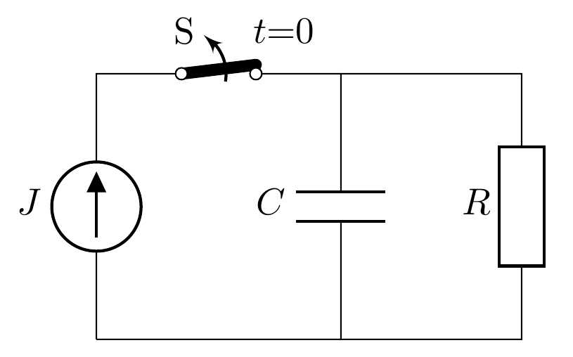
Terminal, meter
\tikzmath{\w1=2.5; \w2=1.0; \w3=1.5; \w4=1.5; \w5=1.5; \h=3;}

\draw
(\w1,\h) to[R, l_=$R_s$, o-] (0,\h)
to[battery2, l=$E_s$] (0,0)
to[short, -o] ++(\w1,0);

\draw
(\w1+\w2,\h) to[short, o-] ++(\w3,0)
to[capacitor, l=$C_{in}$] ++(0,-\h)
to[short, -o] ++(-\w3,0);
\draw
(\w1+\w2+\w3,\h) -- ++(\w4,0)
to[R, l=$R_{in}$] ++(0,-\h)
-- ++(-\w3,0);
\draw
(\w1+\w2+\w3+\w4,\h) -- ++(\w5,0)
to[rmeter, t=V] ++(0,-\h)
-- ++(-\w5,0);\tikzmath{\w1=2.5; \w2=1.0; \w3=1.5; \w4=1.5; \w5=1.5; \h=3;}
\draw
(\w1,\h) to[R, l_=$R_s$, o-] (0,\h)
to[battery2, l=$E_s$] (0,0)
to[short, -o] ++(\w1,0);
\draw
(\w1+\w2,\h) to[short, o-] ++(\w3,0)
to[capacitor, l=$C_{in}$] ++(0,-\h)
to[short, -o] ++(-\w3,0);
\draw
(\w1+\w2+\w3,\h) -- ++(\w4,0)
to[R, l=$R_{in}$] ++(0,-\h)
-- ++(-\w3,0);
\draw
(\w1+\w2+\w3+\w4,\h) -- ++(\w5,0)
to[rmeter, t=V] ++(0,-\h)
-- ++(-\w5,0);
Open voltage
%\usepackage[european,straightvoltages]{circuitikz}

\tikzmath{\w1=2.5; \w2=1.5; \h=2;}

\draw
(0,0) to[open, v^=$\dot{E}$, o-o] ++(0,\h)
to[R, l=$R$] ++(\w1,0)
to[capacitor, l=$C$] ++(0,-\h)
to[short, i_=$\dot{I}$] (0,0);
\draw
(\w1,\h) -- ++(\w2,0)
to[cute inductor, l=$L$] ++(0,-\h)
-- ++(-\w2,0);
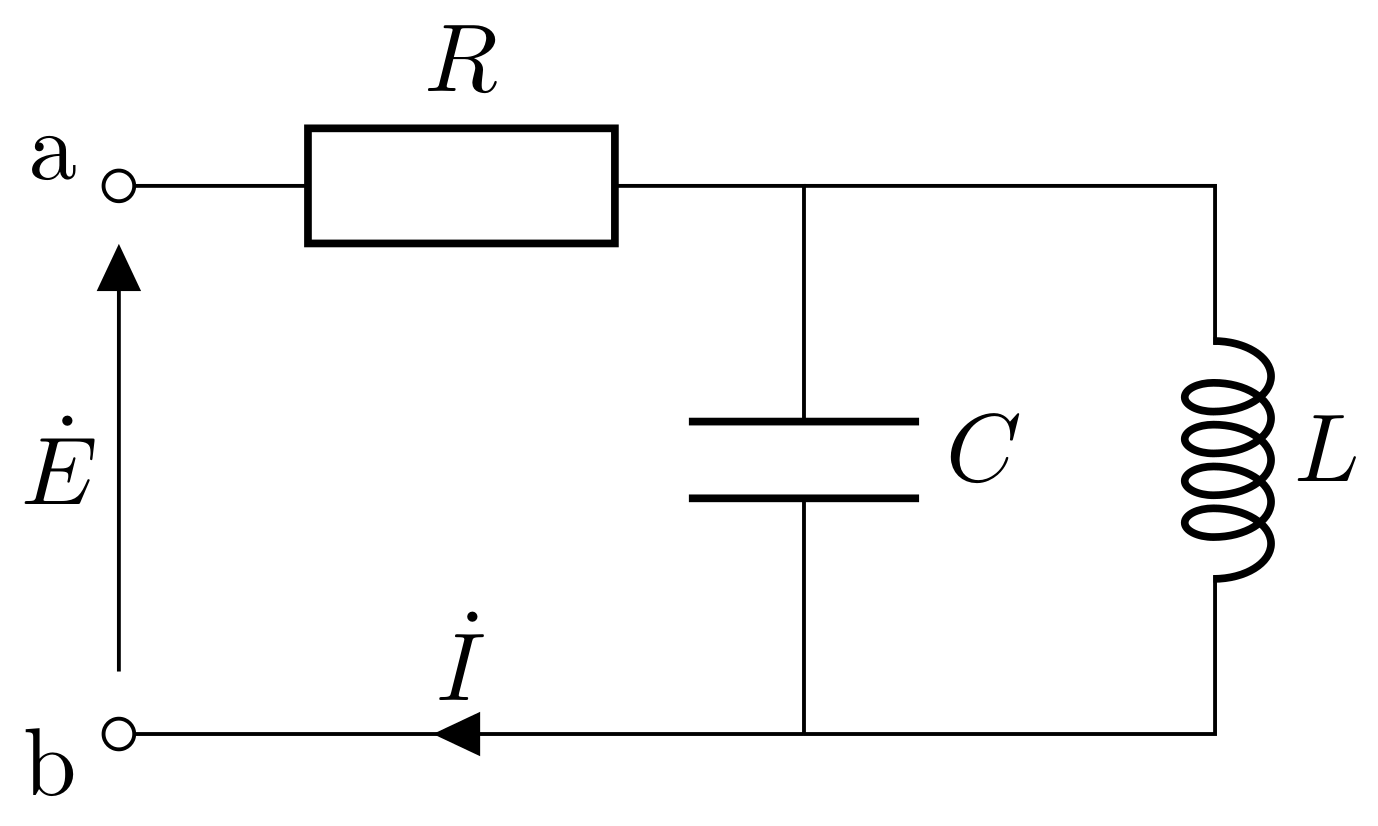
\node at (0,\h)[above=1mm, left=0.3mm] {a};
\node at (0,0)[below=1mm, left=0.3mm] {b};
%\usepackage[european,straightvoltages]{circuitikz}
\tikzmath{\w1=2.5; \w2=1.5; \h=2;}
\draw
(0,0) to[open, v^=$\dot{E}$, o-o] ++(0,\h)
to[R, l=$R$] ++(\w1,0)
to[capacitor, l=$C$] ++(0,-\h)
to[short, i_=$\dot{I}$] (0,0);
\draw
(\w1,\h) -- ++(\w2,0)
to[cute inductor, l=$L$] ++(0,-\h)
-- ++(-\w2,0);
\node at (0,\h)[above=1mm, left=0.3mm] {a};
\node at (0,0)[below=1mm, left=0.3mm] {b};